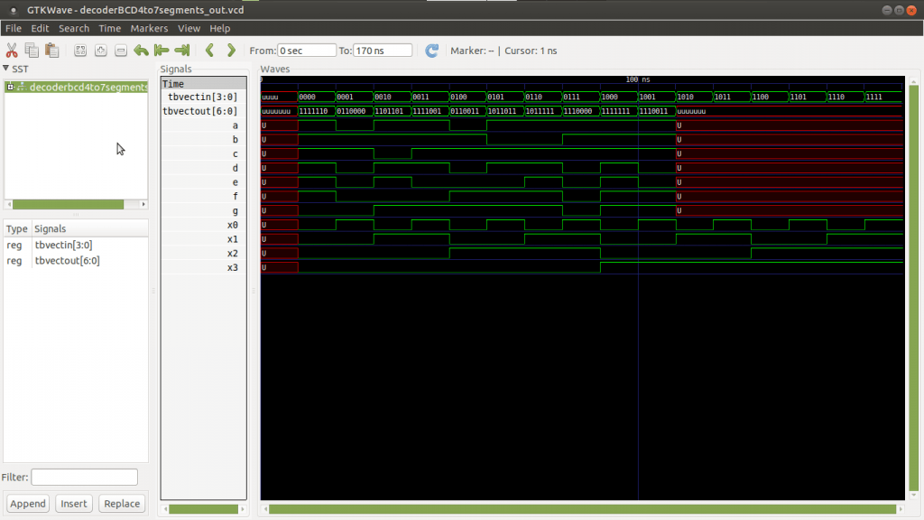
Code-kata para mostrar en un display de siete segmentos números en binario que van desde el 0 al 9. Es un sencillo circuito que se puede encadenar con otros para mostrar los dígitos que sean necesarios. Esto es lo que se llama un decodificador BCD de 4 bits para un display de 7 leds, en este caso.
No tiene mucho que explicar simplemente que es un circuito que convierte las señales de entrada de 4 bits en una señal de salida de 7 bits. Las de entrada son números en binario del 0 al 9. Mientras que las de salida simplemente encienden o apagan los segmentos para pintar el número que toque.
Existen displays de 7, 14, 16 segmentos, más información aquí:
https://es.wikipedia.org/wiki/Visualizador_de_siete_segmentos
Como se indica en Wikipedia, las salidas corresponderán a los leds que hay que iluminar para pintar cada número. También tengo que decir que se pueden codificar no sólo números, sino también letras. Ya dependerá del display que se leerá mejor o peor..
Al grano, el código que define el circuito para 7 segmentos
-- Decodificador BCD para display de leds.
library IEEE;
use IEEE.std_logic_1164.all;

entity decoderBCD4to7segments is
    port (
        a, b, c, d, e, f, g : out std_logic;
        x3, x2, x1, x0 : in std_logic
    );
end entity;

architecture arch of decoderBCD4to7segments is
begin

    -- Decodificamos..
    process (x3, x2, x1, x0)
        variable auxVectOut : std_logic_vector (6 downto 0);
        variable auxVectIn : std_logic_vector (3 downto 0);
    begin

        -- Cargamos entradas al vector auxiliar.
        auxVectIn(3) := x3;
        auxVectIn(2) := x2;
        auxVectIn(1) := x1;
        auxVectIn(0) := x0;

        if auxVectIn = "0000" then auxVectOut := "1111110"; -- 0
        elsif auxVectIn = "0001" then auxVectOut := "0110000"; -- 1
        elsif auxVectIn = "0010" then auxVectOut := "1101101"; -- 2
        elsif auxVectIn = "0011" then auxVectOut := "1111001"; -- 3
        elsif auxVectIn = "0100" then auxVectOut := "0110011"; -- 4
        elsif auxVectIn = "0101" then auxVectOut := "1011011"; -- 5
        elsif auxVectIn = "0110" then auxVectOut := "1011111"; -- 6
        elsif auxVectIn = "0111" then auxVectOut := "1110000"; -- 7
        elsif auxVectIn = "1000" then auxVectOut := "1111111"; -- 8
        elsif auxVectIn = "1001" then auxVectOut := "1110011"; -- 9
        else auxVectOut := "UUUUUUU";
        end if;

        -- Cargamos salidas al vector auxiliar.
        a <= auxVectOut(6);
        b <= auxVectOut(5);
        c <= auxVectOut(4);
        d <= auxVectOut(3);
        e <= auxVectOut(2);
        f <= auxVectOut(1);
        g <= auxVectOut(0);

    end process;

end architecture;
El código para probar el circuito virtualmente, genera el banco de pruebas
Simplemente hace port map del circuito anterior, para inyectarle señales, y recibe las salidas para comprobar visualizando los resultados.
library IEEE;
use IEEE.std_logic_1164.all;

entity decoderBCD4to7segments_tb is
end entity;

architecture arch of decoderBCD4to7segments_tb is

    component decoderBCD4to7segments is
        port (
            a, b, c, d, e, f, g : out std_logic;
            x3, x2, x1, x0 : in std_logic
        );
    end component;

    signal tbVectOut : std_logic_vector (6 downto 0);
    signal tbVectIn : std_logic_vector (3 downto 0);

begin

    unit_unde_test: decoderBCD4to7segments port map (
        a => tbVectOut(6),
        b => tbVectOut(5),
        c => tbVectOut(4),
        d => tbVectOut(3),
        e => tbVectOut(2),
        f => tbVectOut(1),
        g => tbVectOut(0),
        x3 => tbVectIn(3),
        x2 => tbVectIn(2),
        x1 => tbVectIn(1),
        x0 => tbVectIn(0)
    );

    generate_input_signals : process
    begin
        tbVectIn <= "UUUU"; wait for 10 ns;
        tbVectIn <= "0000"; wait for 10 ns;
        tbVectIn <= "0001"; wait for 10 ns;
        tbVectIn <= "0010"; wait for 10 ns;
        tbVectIn <= "0011"; wait for 10 ns;
        tbVectIn <= "0100"; wait for 10 ns;
        tbVectIn <= "0101"; wait for 10 ns;
        tbVectIn <= "0110"; wait for 10 ns;
        tbVectIn <= "0111"; wait for 10 ns;
        tbVectIn <= "1000"; wait for 10 ns;
        tbVectIn <= "1001"; wait for 10 ns;
        tbVectIn <= "1010"; wait for 10 ns;
        tbVectIn <= "1011"; wait for 10 ns;
        tbVectIn <= "1100"; wait for 10 ns;
        tbVectIn <= "1101"; wait for 10 ns;
        tbVectIn <= "1110"; wait for 10 ns;
        tbVectIn <= "1111"; wait for 10 ns;
        report "Simulación terminada.";
        wait;
    end process;

end architecture;
Si todo va bien, al simularlo se deben de ver por pantalla señales como las de la imagen del principio.
gracias ,me sirvió bastante
Me alegro! Y muchas gracias por dejar un comentario! (y)
Eres el put0 amo
No es nada amig0, gracias!
Tengo una duda, si quisiera implementarlo en dos segmentos de 7 bits, seria era el mismo proceso, y como podria anexar las pausas y reset del conteo?
Buenos días Yusdivia!
Lo de este post, digamos, que es la parte del circuito que pinta en un sólo display.
Para hacer con dos displays habría que unirlos con port map, aquí tienes algo más de información:
https://jnjsite.com/vhdl-uniendo-circuitos-un-sumador-completo-de-4-bits/
Para hacer pausas o establecer acciones en el tiempo, los circuitos suelen llevar relojes internos, como el reloj de los microprocesadores, lo mismo tienen otros circuitos o FPGAs:
https://jnjsite.com/vhdl-el-tic-tac-de-un-reloj-a-100-mhzs/
Para llevar un conteo, haría falta diseñar un autómata que haga la cuenta:
https://jnjsite.com/vhdl-construyendo-circuitos-para-automatas/
Un saludo.
Que grande eres bro
Nada hombre, sólo soy uno más compartiendo codekatas.. pero gracias por el comentario!
Un saludo r083r70!
Love you.