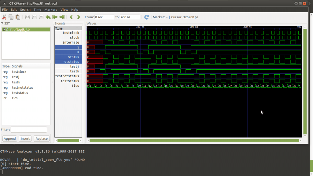
Finalmente llegamos a este code-kata sobre los biestables en VHDL. Este se trata del flip flop JK, que es una combinación de los anteriores posts sobre biestables. Puede almacenar memoria del bit que almacena como el SR, puede resetearse poniéndose a 0, setearse a 1, negarse a si mismo al son del tic tac del reloj como el flip flop T. También se setea o resetea al son del tic tac del reloj como el flip flop D…
En fin, la joya de los biestables.. 😀
En este code-kata dejo una versión que tiene 3 entradas: el pin J, el pin K, y el pin de la señal del reloj. Como salidas, igual que los anteriores posts, tenemos 2 señales (2 pines), que son el estado actual y el negado.
El código fuente del flip flop JK
library IEEE;
use IEEE.std_logic_1164.all;

entity flipFlopJK is
    port (
        status, notStatus : out std_logic;
        clock, j, k : in std_logic
    );
end entity;

architecture arch_flipFlopJK of flipFlopJK is

    signal internalQ : std_logic;

begin

    status <= internalQ;
    notStatus <= not internalQ;

    main_process : process (clock)
    begin

        if rising_edge (clock) then
            report "Procesando tic tac.. clock=" & std_logic'image(clock);
            report "    j=" & std_logic'image(j);
            report "    k=" & std_logic'image(k);

            if j = '0' and k = '0' then
                internalQ <= internalQ;
            elsif j = '0' and k = '1' then
                internalQ <= '0';
            elsif j = '1' and k = '0' then
                internalQ <= '1';
            else
                internalQ <= not internalQ;
            end if;
        end if;
        report "    internalQ=" & std_logic'image(internalQ);

    end process;

end architecture;
El código fuente del banco de pruebas
library IEEE;
use IEEE.std_logic_1164.all;

entity flipFlopJK_tb is
end entity;

architecture arch_flipFlopJK_tb of flipFlopJK_tb is

    component flipFlopJK is
        port (
            status, notStatus : out std_logic;
            clock, j, k : in std_logic
        );
    end component;

    signal testStatus, testNotStatus, testJ, testK : std_logic;
    signal testClock : std_logic := '0';
    signal tics : integer := 0;

begin

    testing_unit: flipFlopJK port map (
        status => testStatus,
        notStatus => testNotStatus,
        clock => testClock,
        j => testJ,
        k => testK
    );

    generate_100Mhzs_clock : process
    begin

        report "Tic tac.. testClock=" & std_logic'image(testClock);
        testClock <= not testClock;

        if testClock = '1' then tics <= tics + 1; end if;
        if tics >= 40 then wait; end if;

        wait for 5 ns; -- Tiempo de espera en un flanco de reloj.

    end process;

    main_process : process
    begin

        wait for 15 ns;
        testJ <= '0'; testK <= '0'; wait for 10 ns;
        testJ <= '0'; testK <= '1'; wait for 10 ns;
        testJ <= '1'; testK <= '0'; wait for 10 ns;
        testJ <= '1'; testK <= '1'; wait for 50 ns;

        testJ <= '0'; testK <= '0'; wait for 10 ns;
        testJ <= '0'; testK <= '1'; wait for 10 ns;
        testJ <= '1'; testK <= '0'; wait for 10 ns;
        testJ <= '1'; testK <= '1'; wait for 50 ns;

        testJ <= '0'; testK <= '0'; wait for 10 ns;
        testJ <= '0'; testK <= '1'; wait for 10 ns;
        testJ <= '1'; testK <= '0'; wait for 10 ns;
        testJ <= '1'; testK <= '1'; wait for 50 ns;
        wait;

    end process;

end architecture;
Terminando, explicaciones y referencias
Para terminar sólo me queda decir que tiene que verse al simularlo un comportamiento como el de la imagen del principio. Me remito para más información a la sección de Wikipedia en donde se explican más detalles muy bien sobre los principales biestables usados en electrónica digital:
https://es.wikipedia.org/wiki/Biestable
Excelente. Me gustarìa saber còmo hacer cuando tengo dos o tres FF
Hola Juan!
Imagino que te refieres a unir varios FF de alguna manera para que actúen en conjunto. Para esto tenemos el port map. Quizá este post te interese:
https://jnjsite.com/vhdl-uniendo-circuitos-un-sumador-completo-de-4-bits/
Un saludo.