Sigo poniéndome al día en electrónica digital, diseñando circuitos digitales. Así que aquí vuelvo con otro code-kata para hacer un sumador de varios bits. Para este sumador reutilizo un componente previamente hecho, diseñando un sumador completo de 4 bits.
Es decir, en un post anterior escribí un sumador completo simple de 1 bit. Ahora con la instrucción de VHDL llamada port map, podemos enlazar tantos componentes como necesitemos en circuitos más grandes. Usando port map es la forma que tenemos de escalar tanto como queramos, todos los circuitos que queramos en sistemas digitales cada vez más grandes.
Al grano, el código fuente del sumador de 4 bits
Me remito al post anterior donde se defino uno de 1 bit. Ahora haciendo port map unimos 4 circuitos de estos para construir uno de 4 bit. Nos puede quedar tal que así:
library IEEE;
use IEEE.std_logic_1164.all;

entity fourBitsFullAdder is
    port (
        sVect : out std_logic_vector (3 downto 0);
        mainCarryOut : out std_logic;
        aVect : in std_logic_vector (3 downto 0);
        bVect : in std_logic_vector (3 downto 0);
        mainCarryIn : in std_logic
    );
end entity;

architecture arch_fourBitsFullAdder of fourBitsFullAdder is

    component oneBitFullAdder is
        port (
            sum, carryOut : out std_logic;
            a, b, carryIn : in std_logic
        );
    end component;

    signal auxCarry : std_logic_vector (4 downto 0);

begin

    auxCarry(0) <= mainCarryIn;

    bit_s0: oneBitFullAdder port map (
        sum => sVect(0),
        carryOut => auxCarry(1),
        a => aVect(0),
        b => bVect(0),
        carryIn => auxCarry(0)
    );

    bit_s1: oneBitFullAdder port map (
        sum => sVect(1),
        carryOut => auxCarry(2),
        a => aVect(1),
        b => bVect(1),
        carryIn => auxCarry(1)
    );

    bit_s2: oneBitFullAdder port map (
        sum => sVect(2),
        carryOut => auxCarry(3),
        a => aVect(2),
        b => bVect(2),
        carryIn => auxCarry(2)
    );

    bit_s3: oneBitFullAdder port map (
        sum => sVect(3),
        carryOut => auxCarry(4),
        a => aVect(3),
        b => bVect(3),
        carryIn => auxCarry(3)
    );

    mainCarryOut <= auxCarry(4);

end architecture;
El banco de pruebas para simular su funcionamiento
Simplemente va sumando 1 bit en cada prueba, no hace más comprobaciones:
library IEEE;
use IEEE.std_logic_1164.all;
entity fourBitsFullAdder_tb is
end entity;
architecture arch of fourBitsFullAdder_tb is
component fourBitsFullAdder is
port (
sVect : out std_logic_vector (3 downto 0);
mainCarryOut : out std_logic;
aVect : in std_logic_vector (3 downto 0);
bVect : in std_logic_vector (3 downto 0);
mainCarryIn : in std_logic
);
end component;
signal testFourBitsA, testFourBitsB, testFourBitsSum : std_logic_vector (3 downto 0);
signal testCarryIn, testCarryOut : std_logic;
begin
unit_under_test : fourBitsFullAdder port map (
sVect => testFourBitsSum,
mainCarryOut => testCarryOut,
aVect => testFourBitsA,
bVect => testFourBitsB,
mainCarryIn => testCarryIn
);
generate_signals : process
begin
testCarryIn <= '0'; testFourBitsA <= "0000"; testFourBitsB <= "0001"; wait for 10 ns;
testCarryIn <= '0'; testFourBitsA <= "0001"; testFourBitsB <= "0001"; wait for 10 ns;
testCarryIn <= '0'; testFourBitsA <= "0010"; testFourBitsB <= "0001"; wait for 10 ns;
testCarryIn <= '0'; testFourBitsA <= "0011"; testFourBitsB <= "0001"; wait for 10 ns;
testCarryIn <= '0'; testFourBitsA <= "0100"; testFourBitsB <= "0001"; wait for 10 ns;
testCarryIn <= '0'; testFourBitsA <= "0101"; testFourBitsB <= "0001"; wait for 10 ns;
testCarryIn <= '0'; testFourBitsA <= "0110"; testFourBitsB <= "0001"; wait for 10 ns;
testCarryIn <= '0'; testFourBitsA <= "0111"; testFourBitsB <= "0001"; wait for 10 ns;
testCarryIn <= '0'; testFourBitsA <= "1000"; testFourBitsB <= "0001"; wait for 10 ns;
testCarryIn <= '0'; testFourBitsA <= "1001"; testFourBitsB <= "0001"; wait for 10 ns;
testCarryIn <= '0'; testFourBitsA <= "1010"; testFourBitsB <= "0001"; wait for 10 ns;
testCarryIn <= '0'; testFourBitsA <= "1011"; testFourBitsB <= "0001"; wait for 10 ns;
testCarryIn <= '0'; testFourBitsA <= "1100"; testFourBitsB <= "0001"; wait for 10 ns;
testCarryIn <= '0'; testFourBitsA <= "1101"; testFourBitsB <= "0001"; wait for 10 ns;
testCarryIn <= '0'; testFourBitsA <= "1110"; testFourBitsB <= "0001"; wait for 10 ns;
testCarryIn <= '0'; testFourBitsA <= "1111"; testFourBitsB <= "0001"; wait for 10 ns;
wait;
end process;
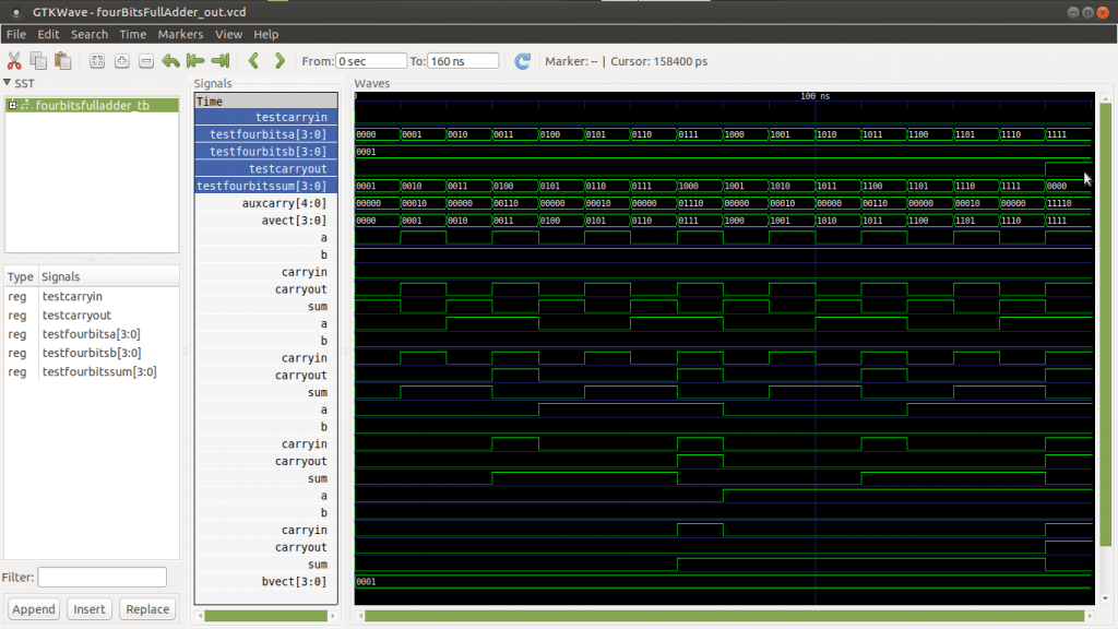
end architecture;Si todo va bien, en la simulación se tiene que ver una gráfica como la de la imagen del principio.
A que se debera este error » wait statement without UNTIL clause not supported for synthesis» porque me aparece y es el unico error para Syntetizar-XST
Hola Carlos.
Hay sentencias de programación VHDL que no son sintetizables, es decir, que no todo lo que se programe en VHDL luego se podrá sintetizar en un circuito.
En los testbench da igual porque son pruebas para visualizar que los circuitos que diseñamos probablemente van a funcionar. Entonces los wait statement de los testbench da igual porque no se van a sintetizar. Si no es un testbench entonces no hay otra solución que modificar el código para no usar sentencias wait sin until.